Inhaltsverzeichnis
Mate Crate
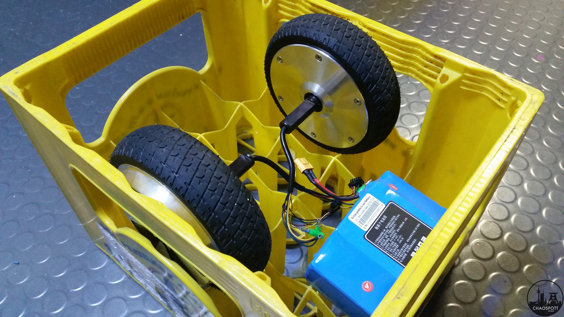
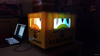
The driving Mate-crate features two 6"-Hoverboard hub motors controlled by one VESC each and a 10S lipo battery pack with 5000 mAh.
Idea
You can find lots of driving beer crates over the net, often powered by petrol engines. Inspired by these crates we wanted to build our own, however we wanted it to be electrically powered.
How it was done
Seeing more and more "Smart-Balance-Scooters" or "Hoverboards" or whatever you like to call them (maybe even "suicide Segway") driving around, we began to wonder, how they are powered and whether we can utilize their components, we began searching the net. We found some hub-motors salvaged from broken down Hoverboards and thought we might give it a try. The advantage of hub motors is the easy mounting and direct drive.
Parts and Stuff
- 2x VESC version 4.12
- 2x Hoverboard Hubmotor
- 5x LiPo 2S 5000mAh
- 7x XT60 Connector Pair
- 1x XT90 Antispark Connector
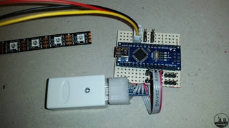
- 1x Arduino Nano
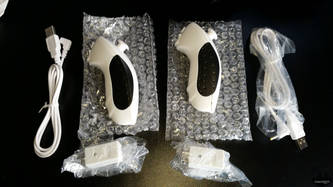
- 1x Wii Nunchuck Clone (Wireless)
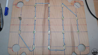
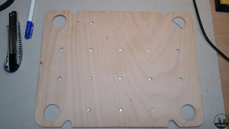
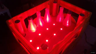
- 16x WS2812b Led's
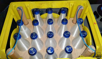
- 16x 3D Print upper half of Matebottle
- 16x Real (Mate) bottle caps
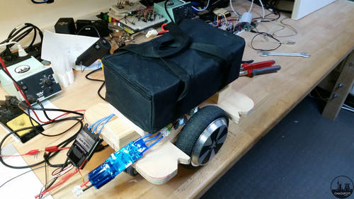
Our first concept was quickly put together:
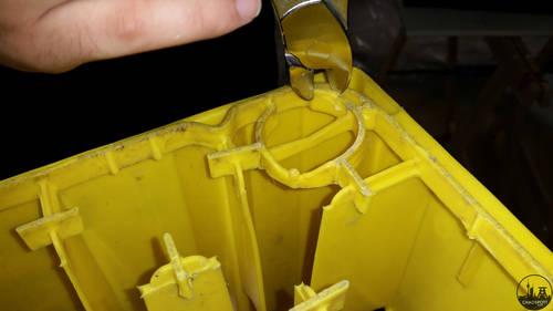
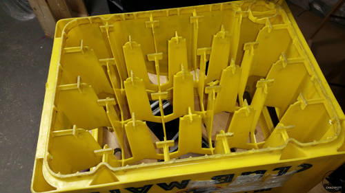
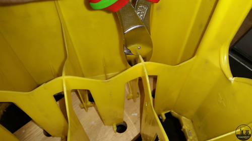
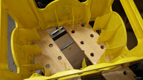
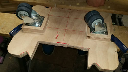
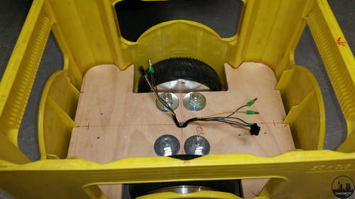
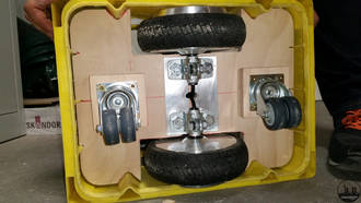
Somehow the wheels must be able to touch the ground, so the inner parts of the crate have to vanish. So get your tools ready and start cutting.
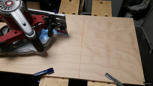
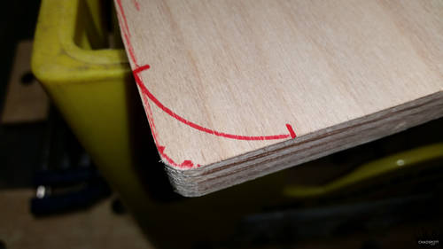
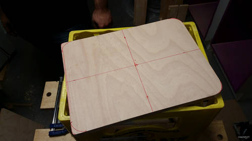
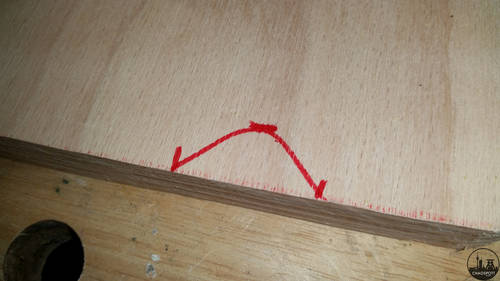
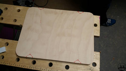
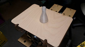
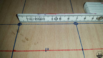
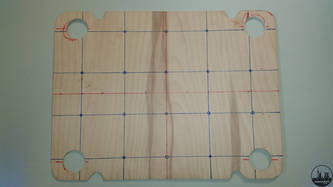
We decided to use wood for the main frame supported by some aluminum elements. We started with a rectangular plate and cut out everything which did not fit into the mate crate.
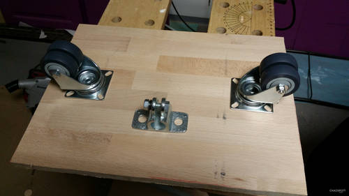
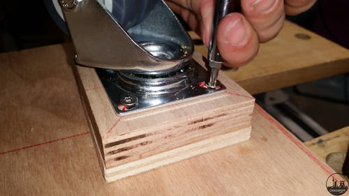
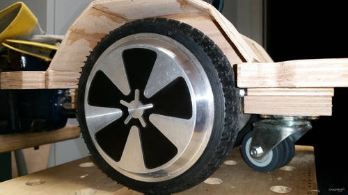
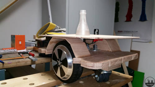
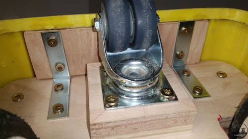
Unlike the original concept of the Hoverboard we didn't want to balance the crate, as it would make controlling the vehicle much more complicated and was found unnecessary anyway. The supporting wheels are castor wheels usually used for furniture transport. They have a diameter of 50mm and can carry a load of 80kg each.
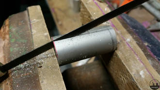
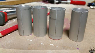
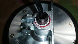
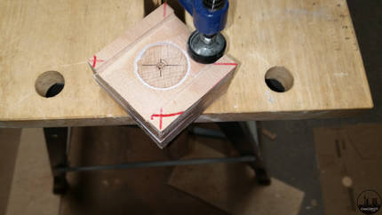
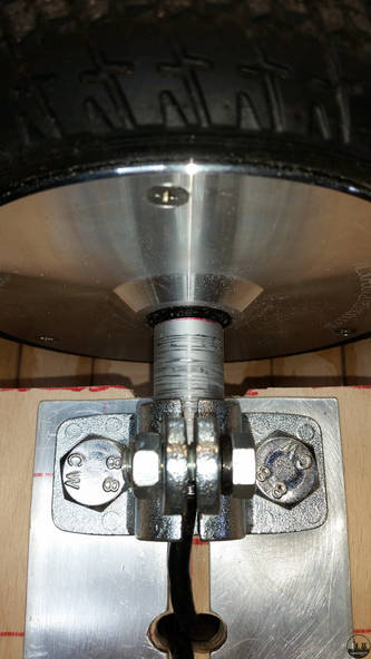
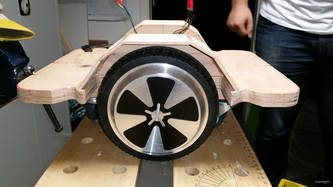
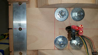
The motor will be held onto the frame by the metal clamp in front of the picture, unfortunately this clamp has an inner diameter of 20mm whereas the motor axle is 16mm in diameter. To fill the 4mm radial gap we used aluminum tubing which was cut once to allow it to shrink. The tubing had an outer diameter of 20mm and a wall-thickness of 1mm.
Unfortunately we did not take pictures of the step showing the marking and cutting out of the first slot for the left motor. So the next step is the mounting of one of the castor wheels.
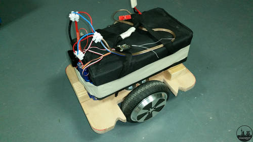
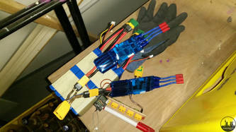
After everything was put together provisional we burrowed a lead-acid battery pack from an e-pocket-bike to run preliminary driving tests. As you might have noticed in the picture, only one VESC is wired to the contraption, the other one is some generic ESC from Hobbyking.
We quickly taped everything in place, wired up one rc-receiver and off it goes. Happy with the basic concept working (more or less), we began adjusting the outer contour to fit perfectly into the mate crate.
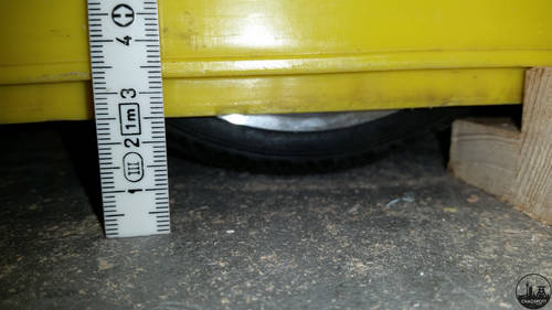
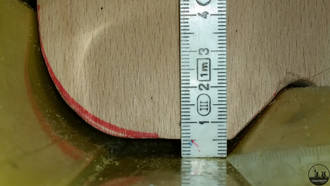
To conceal most of electronics (including the motors) we decided to give the finally assembled crate 25mm clearance. This should be enough to drive around on mostly flat ground (inside buildings we had no problems except on stairs).
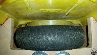
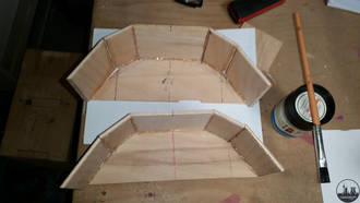
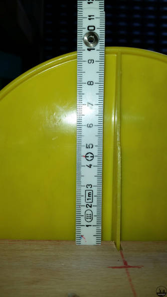
To prevent dust from entering the crate we built wheelhouses. The wheelhouses have a height of 60mm, which allows to add a "lid" that is below the cutouts in the crate.
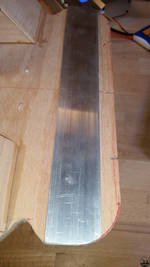
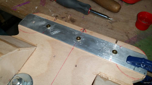
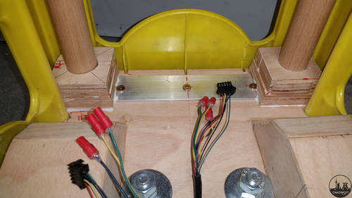
With the center board weakened by the cutouts for the two hub-motors and the load placed on the four corners of the board, we decided to add extra support on the short sides. The support consists of a 40mm x 3mm aluminum bar, screwed onto the main board.
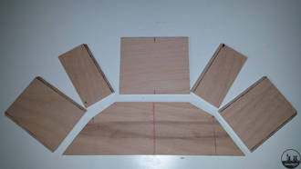
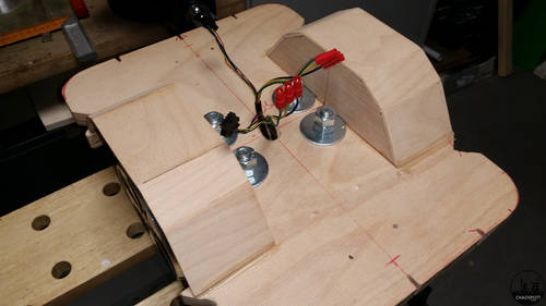
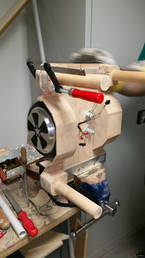
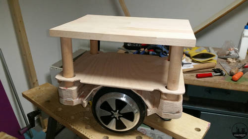
The base of the pillars is supported additionally by gluing them into two layers of cut out board. The base layer has a notch to fit over the aluminum support bar, the first picture also shows the hole drilled into the pillars, so they can be secured by a screw. After gluing the pillars onto the base board, we had to adjust the shape of their supports to fit into the crate.
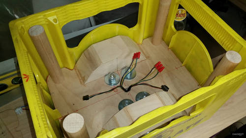
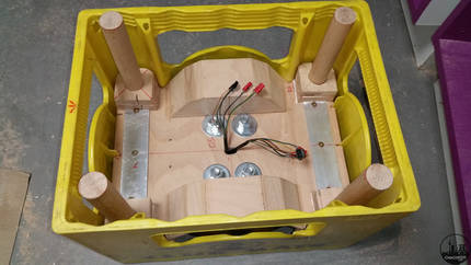
The last picture shows the chassis with all four pillars in place and the "lid" resting on the wheel houses. The driver sits on the large wooden board on top of the whole construction. This board is only hold in place by the Mate-crate to provide easy access to the crates electronics.
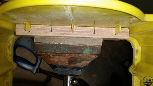
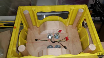
To attach the Mate-crate to the chassis, we first glued another wooden board onto the two short, inner sides of the crate (i.e. front and back side), to prevent the screws from sticking out of the crate while providing enough strength to keep the crate securely fixed to the chassis. The connection between chassis and crate is accomplished with four angle brackets, which allow a fast and easy dismount of the chassis for eventual repairs.
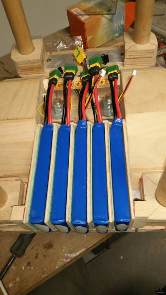
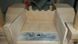
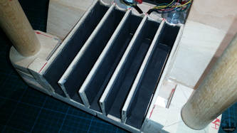
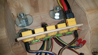
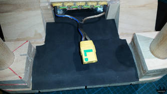
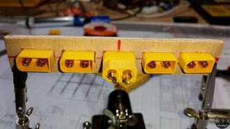
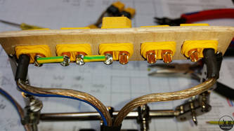
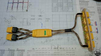
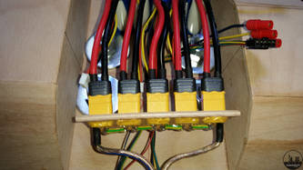
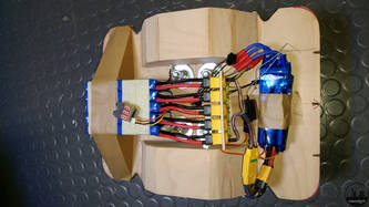
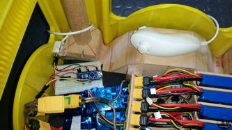
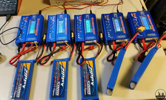
The next step was to fit all the required electronics into the crate (or, to be precise, think of a concept how to store them safely, because we already knew that they would fit if you just toss them in). Beginning with the largest components, we created a safe space for the battery pack(s). The crate is powered by five 2S-5000mAh LiPo battery packs daisy-chained to create one 10S (36V) LiPo pack. We opted for the smaller packs because they were cheaper and easier to recharge (using five battery chargers at once makes this process reasonably fast) and damaging one or two cells doesn't kill the whole battery pack. The harness for our daisy-chain is a row of XT-60 sockets mounted to the chassis ending in a XT-90 anti-spark plug. (The anti-spark plug has two contact points, the one you would reach first when plugging it in has an internal resistor to limit the current. This is helpful when connecting the battery pack to the VESCs as their capacitor-bays act like a short-circuit when empty, which would normally cause a large spark and contact corrosion. Once the plug is fully inserted, the second contact points provides the normal characteristics of the XT-90 plug.)
Size and Weight
- Full Assembly
- standard Club-Mate crate with 2.5cm clearance at the bottom
- round about 10 kg
